Protective angle for the planning of air-termination systems
Reduce the risk of lightning strikes considerably through correct planning
The probability that a lightning current enters a construction system to be protected is reduced considerably by a correctly planned air-termination system. Various methods can be used to plan air-termination systems, one of which is the protective angle method.
The protective angle method is advisable in simple or small buildings and for individual sections of buildings. The use of the protective angle method is recommended where the building is already protected with air-termination rods whose positions were determined using the rolling sphere or grid method. The protective angle method is well suited, for example, to determining the positions of air-termination rods providing merely additional protection for a small number of protruding building parts or structures.
Protective angle method for roof structures
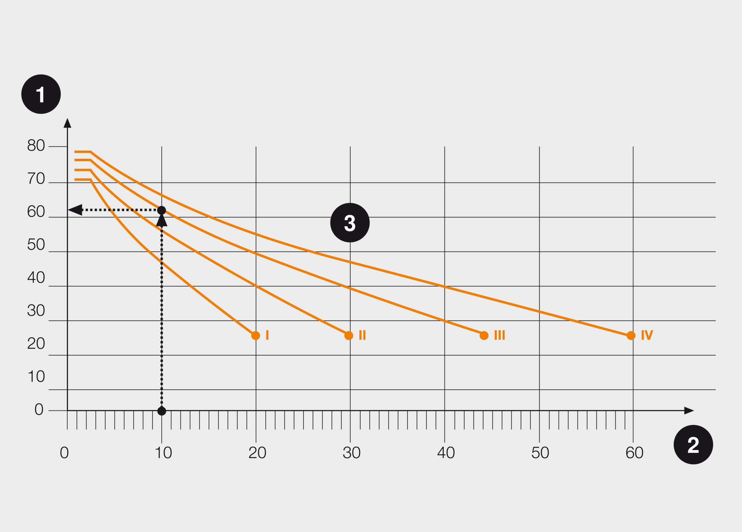
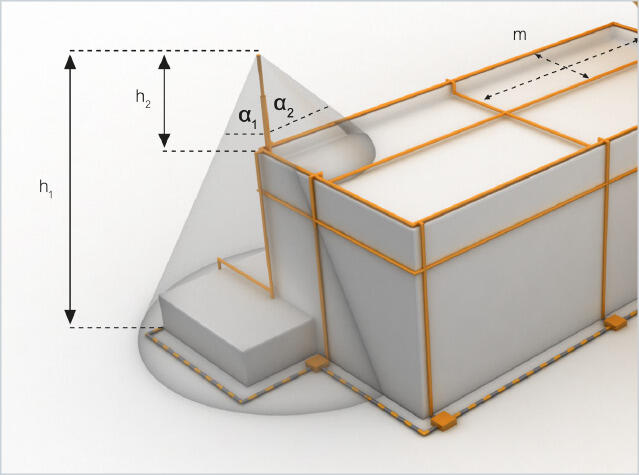
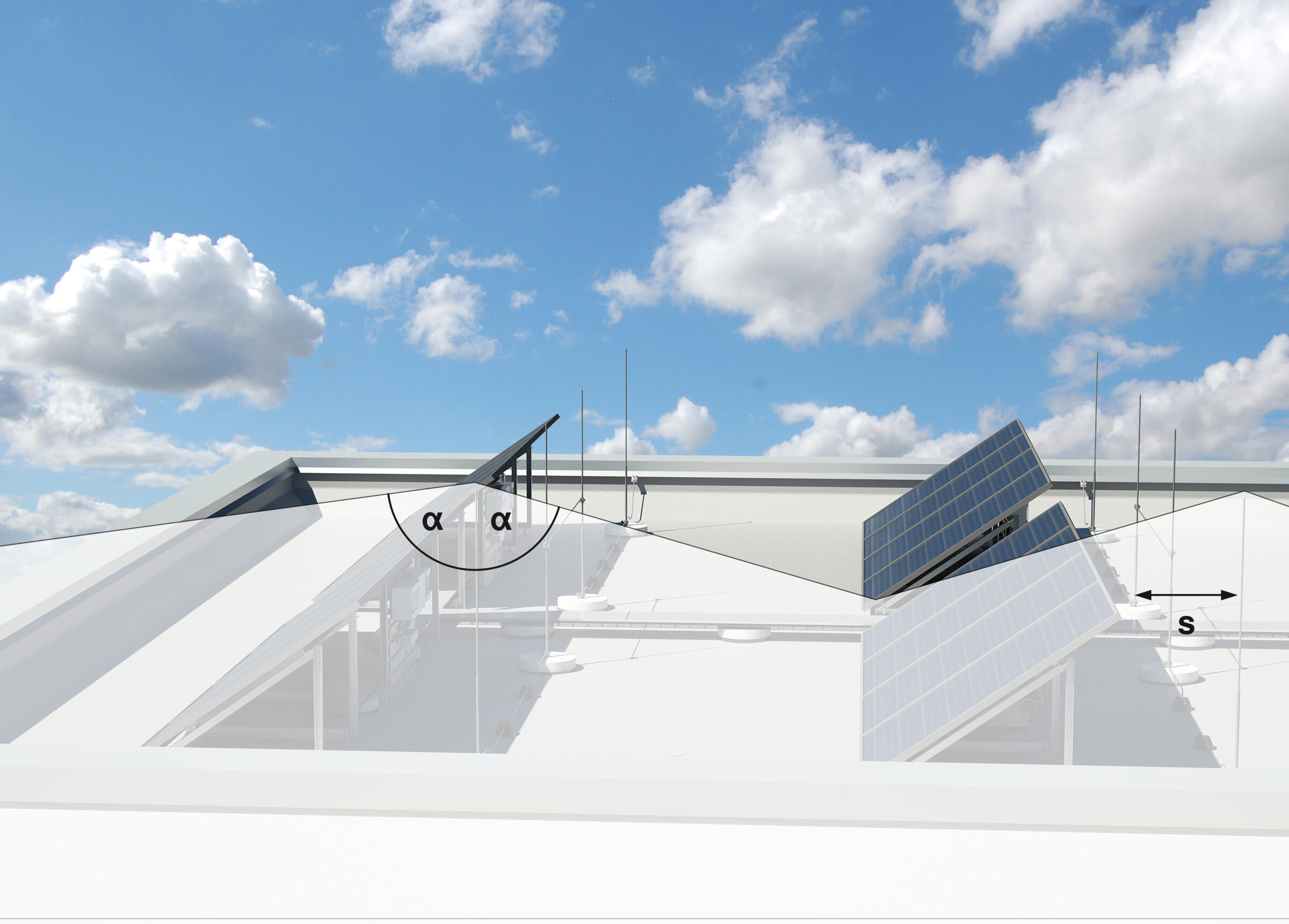
All roof structures must be protected with air-termination rods. Here, it is necessary to observe the relevant separation distance (s) between earthed roof structures and metal systems. If the roof structure has a conductive continuation into the building, e.g. with a stainless steel pipe with a connection to the ventilation or air-conditioning system, then the air-termination rod must be erected at a separation distance of (s) from the object to be protected. This distance safely prevents arcing of the lightning current and dangerous spark creation. The protective angle (α) for air-termination rods varies according to the lightning protection class. The protective angles (α) for the most common air-termination rods of up to 2 m in length are listed in the following table.
Lightning protection class | Protection angle for air-termination rods to 2 m length |
I | 70° |
II | 72° |
III | 76° |
IV | 79° |
Installation principle, building with pitched roof
The protective angle methods can also be clarified in stages using the installation principle of a building with a pitched roof.
Step 1: Determination of the building height
Determine the ridge height of the building. This height is the starting point for planning the entire lightning protection system. The ridge conductor is arranged on the ridge and thus forms the “backbone” for the air-termination system.
Step 2: Determination of the protective angle
Transfer the height of the building to the diagram to read off the protective angle. Then, transfer the protective angle to the building.
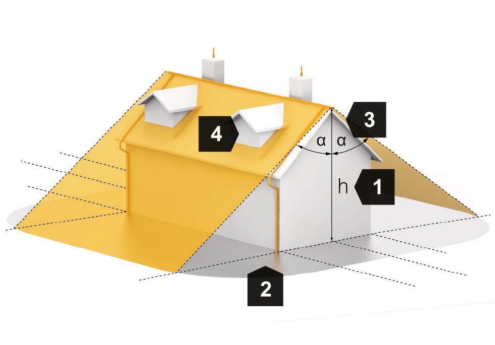
Step 3: Building sections outside the protective angle
Building parts outside of the protected area require additional protection.
Step 4: Completion of the air-termination system
Connect the air-termination system with the conductors. The ends of the ridge conductor should protrude and curve upwards by 0.15 m. This also protects any projecting canopies.